Introduction
The cpld_gengrid program and associated script related functions create the files required for Fix and IC files for the coupled model.
This document is part of the UFS_UTILS documentation.
The cpld_gengrid program is part of the UFS_UTILS project.
Creating Fix and IC files required for the Coupled Model
For the UFS coupled model applications, the following fix files are required, either for IC warmstart creation, at runtime, or for post-processing.
- The CICE6 grid and mask file
- The mesh file for the desired OCN/ICE resolution, which is identical for MOM6 and CICE6.
- The mapped ocean mask on the FV3 tiles
- The ESMF regridding weights required to map a 1/4 deg MOM6 or CICE6 tripole restart file to a lower tripole resolution.
- The latitude,longitude,depth and mask arrays required by WW3 to create a mod_def file for a tripole grid.
- The ESMF regridding weights required to remap the CICE6 or MOM6 output from tripole grid to a rectilinear grid (optional).
Since MOM6 creates the model grid at runtime (including adjusting the land mask, if required), the required files for CICE and UFSAtm must be created in a pre-processing step using only the MOM6 supergrid, topography and land mask files as input. This allows the mapped ocean mask (used for creating of the ATM ICs) and the CICE6 grid and mask files to be consistent with the run-time configuration of MOM6.
Background:
MOM6 grids
The MOM6 supergrid contains a MOM6 grid at twice the desired resolution. The indexing of the supergrid vs the reduced grid is:
        Super Grid               Reduced Grid


    I-1,J+1     I+1,J+1
       X─────X─────X            I-1,J   i,j
       │     │     │               X─────X
       │     │     │               │     │
       │    i│j    │               │  T  │
       X─────X─────X               │     │
       │     │     │               X─────X
       │     │     │          I-1,J-1    I,J-1
       │     │     │
       X─────X─────X
    I-1,J-1     I+1,J-1
MOM6 uses an Arakawa C grid. Within cpld_gridgen, these are referred to as "stagger" locations, and named as follows:
             Bu────Cv─────Bu
             │            │
             │            │
             Cu    Ct     Cu
             │            │
             │            │
             Bu────Cv─────Bu
Rotation angles
For the tripole grid, a rotation angle is defined to translate vectors to/from the grid (i-j) orientation from/to true E-W. The rotation angle on Ct grid points is calculated at run-time in MOM6 (src/initialization/MOM_shared_initialization.F90). However, CICE6 requires a rotation at the corner (Bu) grid points. To find these angles, the rotation angle on Ct points on the opposite side of the tripole fold are used. In cpld_gridgen, these values are found by "flipping over" and changing the sign of the values on the last row of the MOM6 grid. If ipL and ipR are the i-indices of the poles along the last j-row:
            ipL-1     ipL    ipL+1            ipR-1     ipR    ipR+1
               x-------x-------x     |||        x-------x-------x
then after folding along the tripole seam, ipL and ipR must align:
                           ipR+1     ipR    ipR-1
                              x-------x-------x
                           ipL-1     ipL    ipL+1
                              x-------x-------x
Using the folded seam, the values of the rotation on Ct points across the seam are known. The same procedure that CICE uses internally to calculate the Ct angles from the Bu angles can be used to instead calculate the Bu angles knowing the Ct angles.
SCRIP format files
For calculating interpolation weights using ESMF, a SCRIP file needs to be provided. A SCIP file contains the both the grid locations of any stagger grid location (e.g. Ct) and the associated grid vertices for that point. As seen from the above diagram, for the Ct points, those grid vertices are given by the Bu grid locations.
SCRIP requires that the vertices be ordered counter-clockwise so that the center grid point is always to the left of the vertex. In cpld_gridgen, vertices are defined counter-clockwise from upper right. Ct vertices are located on the Bu grid (as shown above), Cu vertices on the Cv grid, Cv vertices on the Cu grid and Bu vertices on the Ct grid. For example, for the Ct grid, the vertices are:
         Vertex #2             Vertex #1
         Bu(i-1,j)             Bu(i,j)
                     Ct(i,j)
       Bu(i-1,j-1)             Bu(i,j-1)
         Vertex #3             Vertex #4
so that the vertices for the Ct grid are found as off-sets of the i,j index of the Bu grid
 iVertCt(4) = (/0, -1, -1,  0/)
 jVertCt(4) = (/0,  0, -1, -1/)
Careful examination of the remaining stagger locations lead to similar definitions for the i,j offsets required to extract the vertices, all of which can be defined in terms of the iVertCt and jVertCt values.
Special treatment is require at the bottom of the grid, where the vertices of the Ct and Cu grid must be set manually (note, these points are on land.) The top of the grid also requires special treatment because the required vertices are located across the tripole seam. This is accomplished by creating 1-d arrays which hold the Ct and Cu grid point locations across the matched seam.
Generating the grid files
The cpld_gridgen program and associated script related functions perform the following tasks:
- read the MOM6 supergrid and ocean mask file and optionally creates the required topo_edits file if the land mask for MOM6 is to be changed at runtime.
- create a master grid file containing all stagger locations of the grid fully defined
- create the CICE6 grid variables and writes the required CICE6 grid file
- create a SCRIP file for the center stagger (
Ct) grid points and a second SCRIP file also containing the land mask - create the ESMF conservative regridding weights to map the ocean mask to the FV3 tiles and write the mapped mask to 6 tile files
- create the ESMF positional weights to map to and from the center
Ctgrid location. - create the EMSF mapping weights to map a tripole grid to a set of rectilinear grids
- use the command line command ESMF_Scrip2Unstruct to generate the ocean mesh from the SCRIP file containing the land mask (item 4)
- use an NCO command line command to generate the CICE6 land mask file from the CICE6 grid file
Using ESMF weights for warmstart generation or for ocean-ice post
The ESMF weights generated by cpld_gridgen are of two types: positional weights and mapping weights. Positional weights are ESMF weights which are used to map to and from the Ct grid location. Mapping weights are weights used to map from one domain to another domain.
In UWM, the ocean and ice always run on the same domain because sea-ice, by definition, can only exist where the ocean exists. The domain of the ocean and ice for the global models is always the tripole grid, which is characterized by three "poles", one in the southern hemisphere and two in the north, both over land.
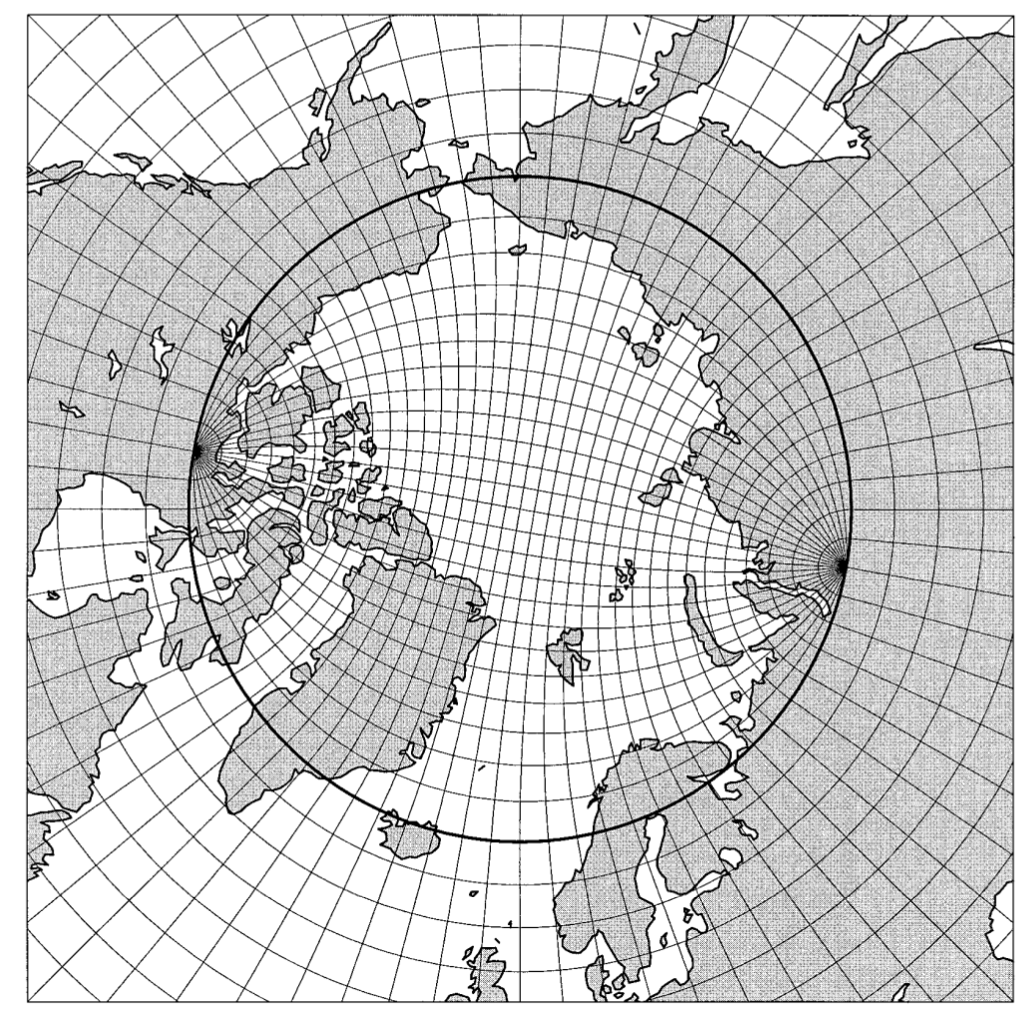
As seen in the figure, in the northern hemisphere, the model grid lines (i.e. indices i,j) do not align with true eastward and northward directions. Therefore, velocities for both MOM6 an CICE6 must be "rotated" from the model orientation to true geographic orientation before mapping can take place. This rotation requires that both components of velocity be co-located at the center Ct grid point and requires a set of positional weights on the source grid. In addition, when mapping from one tripole grid to another, weights are required to re-locate the velocities from the center grid point back to the native velocity locations. This requires a second set of positional weights on the destination grid.
For ocean-ice "post", fields located at the center grid point of the source tripole grid are mapped to a destination rectilinear grid. Thus, both positional weights and mapping weights are generated by cpld_gridgen for use by ocean-ice post. For creation of warmstart files from ocean or ice restart files, the mapping takes place using an ESMF RouteHandle in order to correctly account for differing land masks. Thus, only the positional weights are required for the generation of warmstarts from the restart files.
The generated files
The exact list of files produced by the cpld_gridgen.sh script will vary depending on several factors. To generate positional weights, a SCRIP format file will be produced for each rectilinear destination grid desired as well for each of the grid locations (Cu,Cv or Bu). Positional weights will be generated to Ct on the source grid and from Ct on a destination tripole grid. Note also that multiple intermediate SCRIP format files may be produced depending on the source tripole grid.
- Executing the script for the 1/4 deg OCN/ICE (
mx025) resolution will result in the following files being produced in the output location:
| File name | Description | Function |
|---|---|---|
| tripole.mx025.nc | master grid file | Creating all subsequent grid or mapping files |
| grid_cice_NEMS_mx025.nc | the CICE grid file | used at runtime by CICE6 |
| kmtu_cice_NEMS_mx025.nc | the CICE mask file | used at runtime by CICE6 |
| mesh.mx025.nc | the ocean and ice mesh file | used at runtime by CICE6, MOM6, and CMEPS |
| C[XXX].mx025.tile[1-6].nc | the mapped ocean mask on the ATM tiles | used to create ATM ICs consistent with the fractional grid for a given ATM resolution, where C[XXX]=C48,C96,C192,C384,C768 or C1152 |
- The following mapping files will be produced for use by ocean-ice post:
| File name | Function |
|---|---|
| tripole.mx[source resolution].Ct.to.rect.[destination resolution].[bilinear][conserve].nc | the ESMF weights for mapping variables on the center (Ct) stagger location on the tripole grid to a rectilinear grid with [destination resolution] using either bilinear or conservative mapping |
- The following positional weight files will be produced in the output location for use by both ocean-ice post as well as ocean-ice prep.
| File name | Function |
|---|---|
| tripole.mx[source resolution].[Cu][Cv][Bu].to.Ct.bilinear.nc | the ESMF weights for mapping OCN or ICE |
| tripole.mx[destination resolution].Ct.to.[Cu][Cv][Bu].bilinear.nc | the ESMF weights for mapping warmstart values on a tripole grid from Ct locations to the native stagger locations |
- If run-time land mask changes for MOM6 are requested, the following file will be produced in the output location:
| File name | Function |
|---|---|
| ufs.[Default filename].nc | Topo-edits required for UFS application. These are appended to the existing default topo edits file and implemented at run time with the parameter flag ALLOW_LANDMASK_CHANGES=true. All files produced by the cpld_gridgen.sh will be consistent with this run-time land mask. |